
Meter direction is foundational
An export-control system can only respond correctly if it knows whether the site is importing or exporting. Current-transformer orientation, phase assignment and meter direction must match the exact wiring diagram. Reversed CTs or mismatched phases can make the controller increase output when it should reduce it. These checks belong to qualified electrical commissioning; an owner should not open live switchboards to investigate them.
Confirm the measurement point
The CTs or meter must measure the correct grid connection point for the control objective. Behind-the-meter generation, multiple distribution boards, generators, batteries and parallel grid connections can make a seemingly simple placement incorrect. Record a single-line diagram and the intended point of common coupling so later service does not rely on memory.
Test import and export response under controlled conditions
A commissioning test should verify the sign and magnitude of measured power, then confirm that the inverter responds to an approved export target. Record the target, observed steady-state export, response time and any permitted tolerance from the manufacturer or network rules. The meter and CT accuracy guide explains why a small sensor error can become important near a zero-export limit.
Preserve evidence for future changes
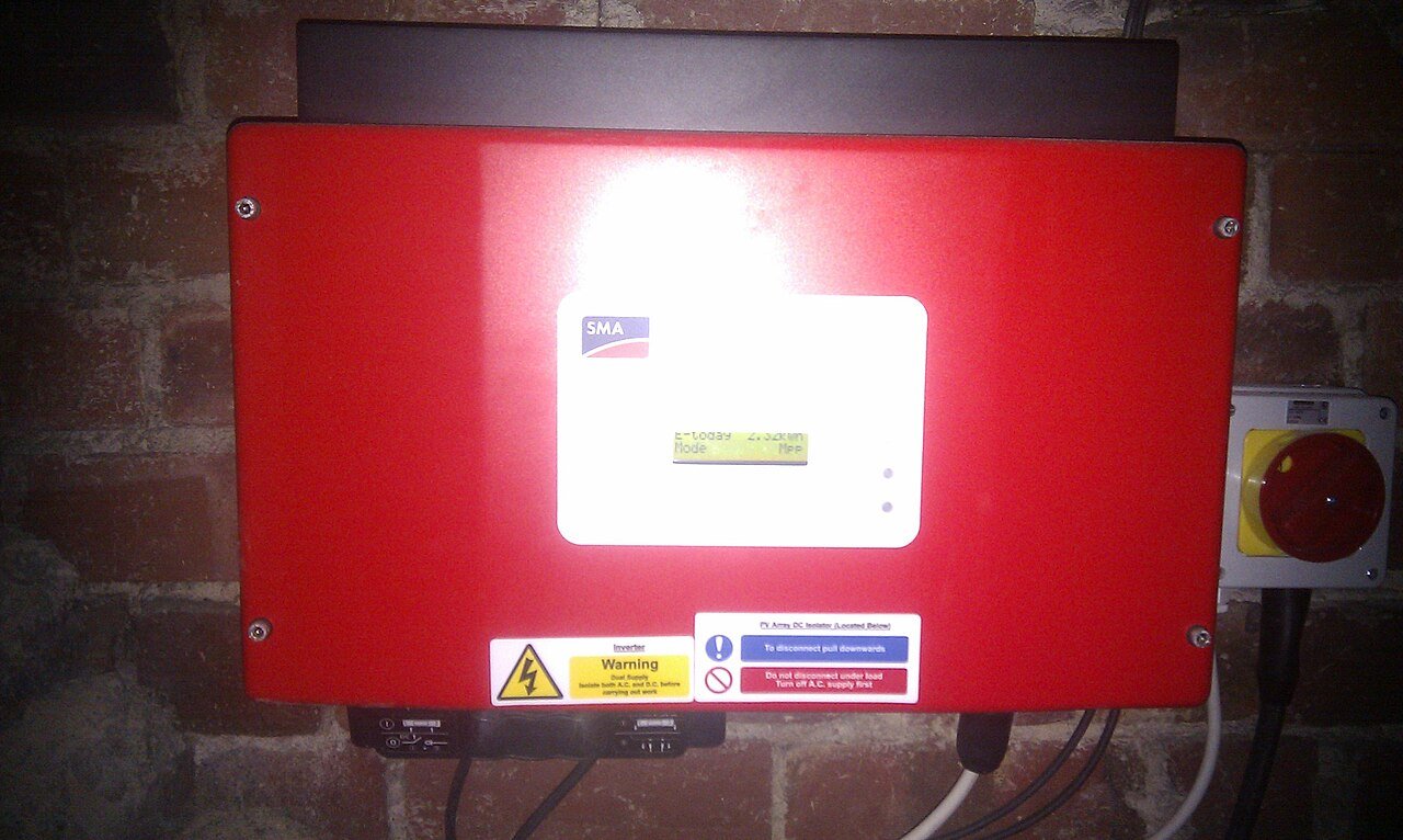
Photograph accessible labels, record meter and CT model numbers, firmware versions and phase mapping, and update documentation if loads or generation are added later. An export limiter that worked when commissioned can become incorrect after switchboard modifications unless the measurement boundary is reviewed.
Retest after major electrical changes
Adding another inverter, battery, generator, large load or a new distribution board can change what the original CTs measure. Treat major electrical alterations as a trigger to review the single-line diagram and recommission export control rather than assuming the original configuration is still valid.